Boilerplate is a good thing to have on the side of a steam locomotive but questionable in the engineering notes for a printed circuit board.
There are many options available to which most of us never give a second thought. The Gerber files contain the traces and outline but rarely the tolerances. Some common specifications are written on the 1-up print in the block. Others show up as notes on a panelization drawing. Many are consolidated in a formal spec sheet.
In general these selected choices work well, so why bother evaluating them for each and every new design? The answers are twofold: performance and price.
 One of the most basic design criterium is the board shape. Round boards show up in instrument clusters and light fixtures. But lacking some peculiarity of the device we commonly choose right-angled boards, square rather than round.
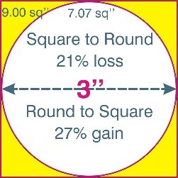
That is with good reason as we want to get as much as possible into the minimum area to control board costs that are calculated on a $/SqIn basis. A round board yields 25% less than a square board, so square corners are better. Or are they always?
Consider handling loss with a square-cornered PCB, particularly a large heavy board. In shipping the forces of a carton tossed onto a truck are concentrated on a sharp corner often resulting in a split box or a damaged board. Within the assembly facility the corners are the weakest point on the board and are there too subject to damage. Better packaging and personnel training would help alleviate the damage but there are two other ways that are in the hands of the PCB designer.
The first method is to add two rails to all boards whether or not arrayed. Most processing equipment use fingers or a standard-sized holders to grip the board during stuffing and soldering but when not required we often decide against the wasted material and cost. For large boards we might be better served by including the rails.
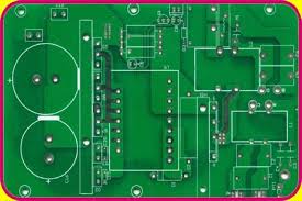
A second method is simply to round the board corners. The area in the corners is usually not used for components, traces, fiducials or tooling holes and could easily be eliminated. The radius need not be great and 0.040” (1mm) to 0.250” might work quite well. If boards are in an array then a router plunge-cut would be necessary to maintain the ability to score the straight sides. This board was laid out square but a rounded corner would render only the small yellow areas unusable.
In some designs rounded corners are contraindicated. Many arrays of small boards are scored. Rounding each corner would necessitate routing instead and this would require both additional space and increased bare board processing time, yielding a higher board cost.
A second concern would be a final installation in which the boards are tiled, lined up side-by-side as in this diagram. Sharp right angles would make the mosaic design look seamless whereas rounded corners would display gaps at the intersections (yellow areas).
Rounded corners are not a solution applicable to all designs but one of the typical boilerplate design features that could bear a review before the board design is put into production.


Comments are closed